Solar Security Cameras for Farms, Parking Lots and Remote Sites
Compare power, connectivity, mounting, autonomy and maintenance needs for solar security cameras on Philippine farms, parking lots and remote sites.
By Maxsol Team

Solar-powered security cameras for farms, parking lots and remote facilities should not be specified as one standard package. Farms often need long boundary coverage despite vegetation and shade; parking sites need clear entrance views and reliable data links; remote facilities usually prioritise autonomy and minimal service visits.
Start by defining what each location must see, how the video will travel, where solar panels can receive unobstructed sunlight, and how soon technicians can reach the equipment. Power systems and wireless links support surveillance, but they do not provide the camera’s imaging, recording or analytics functions.
Farm boundaries and agricultural buildings
Agricultural sites can include gates, access roads, equipment sheds, storage buildings, livestock areas and long property boundaries. These areas rarely have the uniform mounting conditions found in a commercial building.
Coverage planning should distinguish between monitoring a general area and identifying activity at a specific point. A wide view of a field entrance has different camera, lens, lighting and mounting requirements from identification at a gate or monitoring inside a roofed agricultural building.
Shade and seasonal site changes
Trees, crops, building roofs and newly installed structures can affect solar exposure. A panel location that appears clear during one survey may later be shaded by vegetation growth. Dust, leaves, bird droppings and agricultural work can also increase cleaning requirements.
Do not place a solar panel based only on its proximity to the camera. The best camera position and the best solar position may be different. A properly planned design can use a separate panel mount while keeping cable distance, voltage drop and physical protection within acceptable limits.
Mounting on farm structures
Existing poles, gates and lightweight building sections should not automatically be treated as suitable supports. Check:
- Structural condition and resistance to movement
- Exposure to machinery, animals and accidental impact
- Panel orientation and surrounding shade
- Cable routes between the panel, power enclosure and camera
- Access for cleaning without disrupting farm operations
- Protection against water, dust and physical damage
Ingress protection and impact resistance describe different risks. The guide to IP65 and IK10 considerations for outdoor CCTV enclosures explains why a weather-resistant enclosure is not necessarily protected against strong mechanical impact.
Farm connectivity options
A camera near a farmhouse or operations building may connect to an existing network, while a distant gate could require a point-to-point wireless bridge or cellular connection. Terrain, tree lines and buildings can obstruct a radio path even when two points look close on a map.
Wireless equipment must be included in the energy budget. Its continuous load may materially affect daily energy use, especially if the camera also uses infrared illumination, a heater, a fan or local recording hardware.
Parking entrances and open lots
Parking surveillance normally concentrates on entrances, exits, payment points, pedestrian routes and open vehicle areas. The most important view is often narrower and more demanding than general overview coverage.
At an entrance, the design must account for vehicle direction, speed, headlight glare, mounting angle and the required identification detail. Solar power cannot compensate for an unsuitable camera position or imaging specification. Confirm that the selected camera can perform the intended imaging task under actual day and night conditions.
Solar access versus camera placement
Open parking lots may appear ideal for solar equipment, but obstructions can still include trees, signs, roofs and taller vehicles. A camera mounted under a canopy may have good protection and a useful view while receiving little direct sunlight.
Pole-top solar panels can reduce some shade problems, but installers should evaluate wind exposure, pole loading, panel security and maintenance access. Avoid placing panels where cleaning requires technicians to work above active vehicle lanes whenever a safer configuration is available.
Network design for parking areas
Parking areas near an occupied building may use existing Ethernet, fibre or managed wireless infrastructure. Before adding a solar-powered camera, verify:
- Available network connection and port type
- Whether the link supplies power or data only
- Required VLAN and IP addressing
- Recording destination and expected video traffic
- Link monitoring and remote management requirements
- Surge protection and grounding approach
- Failover expectations when the main network is unavailable
Wireless links can be practical where trenching is difficult, but advertised range is not the same as usable application throughput. Vehicle movement, nearby radio networks, obstructions and antenna alignment can influence performance.
Remote facilities with limited service access
Remote pump stations, storage compounds, utility areas, telecommunications sites and isolated project facilities may be costly or slow to visit. For these sites, service access can be as important as the nominal equipment specifications.
A remote system should tolerate the expected interval between inspections without assuming unlimited battery runtime. It should also provide enough information for a technician to determine whether a fault involves the camera, network, power source, battery, controller or upstream recording system.
Autonomy is a system requirement
Battery capacity alone does not establish autonomy. The calculation must account for:
- Camera consumption during day and night operation
- Wireless bridge, cellular router or switch consumption
- Infrared illumination and other variable loads
- Conversion and cable losses
- Controller self-consumption
- Usable battery energy rather than nominal watt-hours
- Reduced solar input during unfavourable conditions
- Battery charging limits at the expected temperature
- Required reserve before a service visit can occur
No nominal battery rating provides a universal 24/7 guarantee. Site conditions, load behaviour, configuration and available solar energy determine actual performance.
Design for diagnosability
Remote equipment should be labelled and documented so technicians can isolate faults efficiently. Where supported by the selected components, useful monitoring points can include battery voltage, charging state, load status, network reachability and controller alarms.
Monitoring does not eliminate maintenance. A working network connection may show that a device is online, but it cannot confirm that a panel is clean, a mount is secure or an enclosure seal is undamaged.
Compare power, connectivity and mounting needs
The following matrix shows typical differences among three hypothetical design scenarios. It is a planning aid, not measured product performance or a recommendation for a particular camera model.
| Requirement | Farm boundary or building | Parking entrance or open lot | Remote facility |
|---|---|---|---|
| Coverage priority | Gates, sheds, livestock areas and long boundary segments | Entrances, exits, pedestrian routes and vehicle areas | Critical equipment, perimeter access and operational status |
| Common shade concerns | Trees, crops, roofs and seasonal vegetation growth | Canopies, signs, buildings, landscaping and large vehicles | Terrain, structures and limited choice of mounting position |
| Mounting approach | Existing buildings or purpose-built poles, with impact protection where machinery or animals are present | Elevated poles or structures positioned to avoid vehicle conflict | Robust independent mount designed for infrequent inspection |
| Connectivity | Existing farm network, point-to-point wireless or cellular | Ethernet, fibre, managed wireless bridge or cellular backup | Directional wireless or cellular, depending on infrastructure and terrain |
| Autonomy priority | Moderate to high, depending on distance from occupied buildings | Moderate where service access is straightforward; higher for isolated lots | High where technician visits are difficult or delayed |
| Service access | May depend on farm schedules, road condition and equipment movement | Usually accessible, but work may need traffic control | Potentially limited by distance, weather, site permission or transport |
| Main design risk | Vegetation and changing obstructions | Imaging angle, glare, traffic exposure and network integration | Underestimated loads, poor diagnostics and long outage duration |
These categories should not be used as automatic sizing rules. For example, a remote farm gate may require more reserve than a fenced utility site with regular inspections. Conversely, a parking system with several radios and cameras may use more energy than a single remote-site camera.
Select components by measured requirements
Component selection should begin only after measuring or confirming the complete load. Use equipment datasheets as an initial reference, then verify actual operating consumption for the intended configuration where practical.
For a structured calculation, follow the process in this guide to sizing an off-grid solar power system for CCTV. The essential inputs are daily watt-hours, required reserve, expected solar input, conversion losses and the controller’s supported electrical limits.
A hypothetical load example
Assume, purely as a hypothetical design example, that a camera and network device draw a combined average of 12W:
- Daily energy demand: 12W × 24 hours = 288Wh per day
- Three days of theoretical load energy: 288Wh × 3 = 864Wh
The 864Wh figure is not a battery recommendation. It excludes conversion losses, controller consumption, battery operating limits and the energy required to restore charge after low-sun conditions. Nominal battery watt-hours are not fully usable delivered energy.
If the same system rises to a hypothetical 20W average because of night illumination or additional networking hardware, daily demand becomes 480Wh. This difference shows why installers should not size a system from the camera’s daytime rating alone.
Solar power examples to evaluate
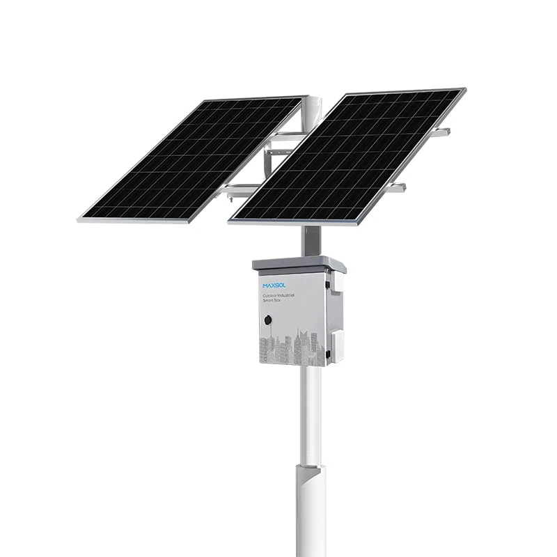
The Maxsol CS12060 120W and 768Wh solar power system documents a 120W monocrystalline panel, a 12.8V 60Ah 768Wh LiFePO4 battery, MPPT control and three DC12V outputs. RS485 is optional. These specifications make it a component-selection reference, not proof that it can support a particular camera or required autonomy.
For a calculated load requiring a different panel and nominal storage category, the Maxsol CS400150 400W and 1920Wh solar power system documents two 200W panel modules, a 12.8V 150Ah 1920Wh LiFePO4 battery, MPPT control and four DC12V outputs.
The linked systems supply DC power; they do not provide camera imaging or video recording. They are also not established as tested bundles with the wireless product or any unspecified camera. For either system, confirm the current datasheet and supplied configuration, including:
- Controller PV voltage, current and power limits
- Battery charging temperature limits
- Available protection functions
- Output voltage and connector arrangement
- Combined output current requirements
- Cable size and permitted cable length
- Monitoring interface, if required
Wireless connectivity example
Where a clear point-to-point path is available, the Maxsol CPE295 5.8GHz directional wireless CPE documents a 2×2 14dBi directional MIMO antenna, one Gigabit LAN port, IEEE 802.3af/at or 9–48V DC power support and 6.5W full-load consumption.
Its power demand must be added to the solar calculation. Its product range and wireless rate labels do not guarantee usable site distance or application throughput. Verify line of sight, Fresnel-zone clearance, interference, mounting alignment, network capacity and applicable local radio rules.
Prepare a requirements handover
A procurement or installation handover should contain measured requirements rather than general descriptions such as “solar CCTV for a remote site”. At minimum, record:
- Coverage objective: What activity, person, vehicle or asset must be observed?
- Camera requirement: Resolution, lens, night operation, analytics and recording method.
- Measured load: Normal, peak and night consumption for every powered device.
- Power interface: Voltage, allowable variation, connector and startup current.
- Solar survey: Panel location, orientation constraints and present or seasonal shade.
- Autonomy target: Required operating period without useful charging, stated as a design requirement rather than a guarantee.
- Network path: Ethernet, fibre, directional wireless or cellular, including expected traffic.
- Mounting details: Pole or structure, height, wind exposure, impact risk and access method.
- Environment: Water, dust, heat, corrosion exposure, pests and potential vandalism.
- Service plan: Inspection interval, travel constraints, spare parts and responsible team.
- Management needs: Local indicators, remote monitoring, alarms, logs and reset methods.
- Acceptance criteria: Tests and records required before project sign-off.
This handover allows designers, installers and buyers to compare offers on the same basis.
Plan maintenance and acceptance checks
Solar camera systems require planned inspection even when they have no connection to the electrical grid. Maintenance frequency should reflect the site environment, cleaning rate, access difficulty and operational importance.
Routine maintenance checklist
Inspect and document:
- Solar panel cleanliness, physical damage and shading
- Panel bracket, pole and fastener condition
- Cable movement, abrasion and exposed connectors
- Enclosure seals, cable glands and drainage
- Battery and controller status where monitoring is available
- Camera focus, view direction and night image quality
- Wireless antenna alignment and link condition
- Recording continuity and system time
- Grounding and surge-protection components
- Vegetation or new structures affecting the solar or radio path
For farms, include checks after substantial vegetation growth or changes to working areas. For parking sites, inspect after pole impact or site-layout changes. For remote facilities, use each visit to gather enough condition data to plan the next service interval.
Acceptance tests before handover
Commissioning should verify more than whether live video appears on a screen. The acceptance process should include:
- Confirming the camera view against the stated coverage objective
- Testing daytime and night-time imaging under realistic conditions
- Recording actual device consumption in intended operating modes
- Confirming controller, panel and battery configuration
- Checking output voltage at the load under operation
- Testing network throughput, latency and stability as required
- Verifying recording, playback and event retrieval
- Simulating power interruption and recovery where safe
- Confirming labels, diagrams, passwords and configuration backups
- Photographing panel, enclosure, cable and antenna installations
- Recording baseline power and network readings for future troubleshooting
Do not treat a short commissioning period as proof of long-term autonomy. Acceptance should confirm installation quality and operation against defined criteria, while ongoing energy performance must be reviewed across relevant site conditions.
The practical next step is to compare the linked Maxsol power and wireless models against the project’s measured load, output and port count, radio distance, line of sight, environmental exposure, reserve target and management requirements. Confirm current datasheets and supplied configurations before specifying any component as part of the final camera system.