MPPT vs PWM for Outdoor Solar Power in the Philippines
Compare MPPT and PWM controllers for outdoor solar systems, including voltage matching, LiFePO4 checks, seasonal yield, limits and total cost.
By Maxsol Team

For most outdoor CCTV, wireless networking and remote monitoring systems, MPPT is the more flexible choice when panel voltage is higher than battery voltage, cable runs are long, solar conditions vary or future expansion is possible. PWM can still be appropriate for a small, cost-sensitive system where the solar panel and battery voltages are closely matched.
The decision should not be based on the controller label alone. Check panel open-circuit voltage, array current, controller charge-current limits, standby demand, battery charging profile and operating temperature. MPPT tracking efficiency is not the same as complete system efficiency, and neither controller type can compensate for an undersized panel, excessive load or unsuitable battery.
How MPPT and PWM charge controllers operate
Both controller types regulate power from a solar panel or array before it reaches the battery. The difference is how each controller manages panel voltage and charging current.
How a PWM controller works
A pulse-width modulation or PWM controller switches the connection between the panel and battery rapidly to regulate charging. When connected, the panel generally operates close to the battery’s charging voltage rather than at its own maximum-power voltage.
This approach is straightforward and can work effectively when:
- The panel is intended for the battery’s nominal voltage.
- Panel voltage remains suitable across expected temperatures.
- The cable run is short enough to control voltage drop.
- The load and array are small.
- Low purchase cost is more important than design flexibility.
The main limitation is that any difference between the panel’s available operating voltage and the battery voltage cannot normally be converted into additional charging current. Some potential panel power may therefore remain unused.
How an MPPT controller works
A maximum power point tracking or MPPT controller searches for the panel voltage and current combination that produces the most available power under current conditions. A DC-to-DC conversion stage then changes that input into the voltage and current required for battery charging.
This allows a higher-voltage panel or series-connected array to charge a lower-voltage battery, provided every input limit is respected. It can also reduce array-side current for a given power level, which may help manage voltage drop over longer panel-to-controller cable runs.
MPPT is commonly favoured when:
- The panel’s maximum-power voltage is substantially above battery voltage.
- The array must operate over long cables.
- Panel temperature and irradiance vary.
- The system has a larger energy requirement.
- Array configuration or later expansion requires more flexibility.
However, “MPPT” does not automatically mean that the entire solar system is highly efficient. Tracking performance is only one part of the energy path. Cable losses, converter losses, controller standby consumption, battery charging acceptance, BMS behaviour, panel temperature, shading and load-side conversion all affect delivered energy.
| Comparison point | PWM | MPPT |
|---|---|---|
| Basic operating method | Switches panel connection to regulate battery charging | Tracks available panel power and converts voltage and current |
| Panel-to-battery voltage relationship | Best with closely matched nominal voltages | Can accept higher PV voltage within controller limits |
| Long PV cable runs | Often less flexible because lower voltage means higher current for the same power | Higher array voltage may help reduce cable current and voltage drop |
| Small-system simplicity | Generally strong | More features and design variables to verify |
| Standby demand | Often lower, but confirm the exact model | Can be higher because of tracking and conversion electronics |
| Expansion flexibility | Usually limited by close voltage matching | Often better, subject to PV voltage, current and power limits |
| Purchase cost | Commonly lower | Commonly higher |
| Best-fit use | Small, closely matched and cost-sensitive systems | Variable conditions, larger loads, higher panel voltage or longer cable runs |
Panel and battery voltage matching
Voltage matching is the first practical difference in an MPPT vs PWM solar charge controller outdoor system.
With PWM, a “12V nominal” battery typically needs a panel designed to provide suitable charging voltage for that battery class. Nominal labels are not enough: compare the panel’s maximum-power voltage, open-circuit voltage and temperature behaviour with the battery’s required charging voltage and the controller’s limits.
If the panel voltage is much higher than the battery voltage, PWM generally does not convert the excess voltage into extra output current. MPPT can perform that conversion, although actual output still depends on available sunlight, operating temperature and conversion losses.
A simplified hypothetical illustration
Assume, purely for illustration, that a panel is operating at 20V and 5A, or 100W, while a battery is charging at 13.5V. These are hypothetical assumptions, not measured product performance.
A simplified PWM calculation would place panel current near 5A while panel voltage is pulled closer to the battery’s charging voltage:
- Approximate charging power before other losses: 13.5V × 5A = 67.5W
An MPPT controller could theoretically convert more of the available 100W input into a lower voltage and higher charging current, minus conversion, wiring and environmental losses.
This illustration is not a promised efficiency gain. A panel rarely operates continuously at its nameplate power, and controller behaviour differs by model. When panel and battery voltages are already closely matched, the practical MPPT advantage may be modest.
Check more than the nominal voltage
Before selecting a controller, verify:
- Maximum PV open-circuit voltage: Calculate array Voc at the lowest expected panel-cell temperature, then keep it below the controller’s specified limit with appropriate design margin.
- PV operating-voltage range: Confirm that array voltage remains inside the MPPT tracking range or the PWM controller’s usable range.
- Maximum PV input current: Check array short-circuit current and parallel-string current against the controller’s input rating.
- Maximum PV power: Do not assume that a high voltage limit also permits unlimited panel wattage.
- Maximum battery charge current: MPPT conversion can produce battery-side current higher than array-side current.
- System voltage: Confirm support for the actual battery configuration, not just a “12V” or “24V” marketing label.
- Cable voltage drop: Assess both the panel-to-controller and controller-to-battery conductors.
The controller should normally be installed close enough to the battery to limit battery-side voltage drop. Otherwise, the controller may measure a higher voltage at its terminals than the battery actually receives, causing charging to reduce too early.
Temperature, shading and seasonal yield
Outdoor solar design in the Philippines must account for heat, cloud variation, shading and site-specific seasonal conditions. Do not choose a controller using panel nameplate wattage alone.
Cold-weather Voc still matters
Solar panel open-circuit voltage rises as cell temperature falls. Although many Philippine installations face heat more often than extreme cold, cooler high-elevation sites, exposed locations and clear early mornings can still produce a higher Voc than standard test-condition values.
Use the panel manufacturer’s temperature coefficient and the lowest credible cell temperature for the site. If the calculated array Voc exceeds the controller’s maximum PV voltage, the controller may be damaged. MPPT does not remove this risk.
Heat can reduce voltage and controller output
As solar cells become hotter, their operating voltage usually falls. This can reduce available panel power and may leave insufficient voltage headroom for charging if the array is poorly matched.
Controllers installed inside sealed outdoor boxes may also reduce output when internal temperature rises. Check:
- Rated operating-temperature range
- Charge-current derating information
- Required clearance and ventilation
- Enclosure temperature under solar exposure
- Distance from batteries and other heat-producing equipment
A larger current rating does not guarantee full output at every enclosure temperature.
MPPT cannot recover energy blocked by shade
MPPT can adjust to a changing panel power curve, but it cannot restore irradiance lost to a pole, antenna, tree, building edge, cable bundle or dirt. Partial shading can also create multiple possible power points, and controller tracking behaviour varies.
For outdoor surveillance and wireless sites, inspect shading at different times of day and during different seasons. A shadow that appears minor during commissioning may cross a critical section of the panel later in the year.
Other practical checks include:
- Keep antennas, cameras and cabinet doors from shading the panel.
- Review whether nearby vegetation may grow into the solar window.
- Confirm bypass-diode and string arrangements for multi-panel arrays.
- Position the panel for the site’s required energy season, not only the day of installation.
- Use site-specific solar-resource inputs rather than assuming uniform conditions nationwide.
Seasonal yield depends on the complete energy balance. A high tracking percentage cannot guarantee runtime when the array, battery or load allowance is inadequate. For the broader calculation process, see this guide to sizing an off-grid solar power system for CCTV.
LiFePO4 charging profile and BMS checks
A controller must support the battery’s required charging profile. Selecting an MPPT unit does not guarantee compatibility with every LiFePO4 battery.
Confirm the following with the current battery and controller documentation:
- Bulk or absorption charging voltage
- Float-voltage requirement, if any
- Absorption duration or termination method
- Maximum permitted charge current
- Charging-temperature range
- Low-temperature charging cutoff
- High-temperature protection
- Equalisation settings
- Controller behaviour after a BMS disconnect
- Low-voltage disconnect and reconnect thresholds
- Recovery after the battery reaches a protection state
Traditional lead-acid settings may apply prolonged absorption, float charging, equalisation or temperature compensation that is not appropriate for a particular LiFePO4 battery. Use a dedicated LiFePO4 profile or a properly configurable controller, following the battery supplier’s limits.
Coordinate the controller with the BMS
The battery management system protects the cells, but it should not be treated as the normal charge-control mechanism. If the controller repeatedly drives the battery into BMS overvoltage, overcurrent or temperature protection, the system may disconnect and reconnect unpredictably.
Some controllers also need a stable battery connection before they can start or identify system voltage. After a BMS disconnects the battery, verify whether the controller:
- Restarts automatically
- Retains its configured battery profile
- Resumes charging safely
- Requires PV isolation before battery reconnection
- Reports the event through available monitoring
Charging below the battery’s permitted temperature can be particularly important at cooler sites. A controller with temperature sensing is not enough unless its behaviour matches the battery’s limits and the sensor measures a relevant location.
For more battery-specific context, review the practical benefits and limits of LiFePO4 batteries in solar CCTV systems.
Compare total cost and controller limits
PWM may have a lower initial controller cost, while MPPT may reduce other system costs or improve design flexibility. The better commercial choice depends on the whole installation rather than the controller price alone.
Consider these lifecycle factors:
| Cost or design factor | Questions to ask |
|---|---|
| Solar panel requirements | Does PWM require a more closely matched module? Could MPPT support a higher-voltage array without exceeding input limits? |
| Cable size and distance | Will lower array current allow a practical cable size, or is the run already short? |
| Battery charging | Does the controller provide the exact LiFePO4 profile and current limits required? |
| Standby energy | How much current does the controller consume overnight and during low-light periods? |
| Thermal design | Can it supply the required charge current inside the intended enclosure temperature? |
| Monitoring | Is local or remote status reporting required, and what additional standby demand does it add? |
| Maintenance | How easy is it to diagnose PV, battery, load and temperature faults? |
| Expansion | Is there enough PV voltage, current, power and charge-current headroom for planned changes? |
| Service impact | What is the operational cost of insufficient charging or avoidable site visits? |
Standby consumption deserves particular attention in small systems. A controller drawing a seemingly minor current continuously can become a meaningful overnight load relative to a low-power camera, radio or sensor installation. Compare datasheet figures in each operating state, including sleep, night and communications modes.
Also distinguish controller input current from output charge current. In a hypothetical 120W, 12V-class system, battery-side charging current might approach 10A before real-world losses and voltage variation. That does not mean the panel itself supplies 10A at its higher operating voltage. The controller must be rated for both sides of the conversion.
Do not size directly to the controller’s absolute maximum. Consider manufacturing tolerances, temperature, irradiance variation, current surges, array expansion and any manufacturer-required margin. If two source documents show conflicting limits, request or use the current authoritative datasheet rather than selecting the more convenient value.
When each controller approach is appropriate
Choose PWM when the system is simple and closely matched
PWM may be reasonable when all of these conditions apply:
- The battery and panel are designed around a compatible nominal voltage.
- The panel cable is short.
- The array is small and unlikely to expand.
- The controller supports the required battery profile.
- Standby consumption is especially important.
- Energy modelling shows enough seasonal margin despite PWM operation.
- Lower initial cost provides a meaningful project benefit.
PWM is not inherently unsuitable for outdoor use. Its success depends on correct voltage matching and sufficient energy margin. Avoid using it merely because the battery is labelled “12V”; the actual charging and panel operating voltages still need to be checked.
Choose MPPT when flexibility and energy capture matter
MPPT is generally the stronger option when one or more of these conditions apply:
- The panel voltage is substantially higher than battery voltage.
- The PV cable run is long.
- The site experiences changing panel temperatures or irradiance.
- The load is significant relative to available panel area.
- The project may add panels or loads later.
- Monitoring or configurable charging is required.
- A small improvement in harvested energy could reduce low-battery events.
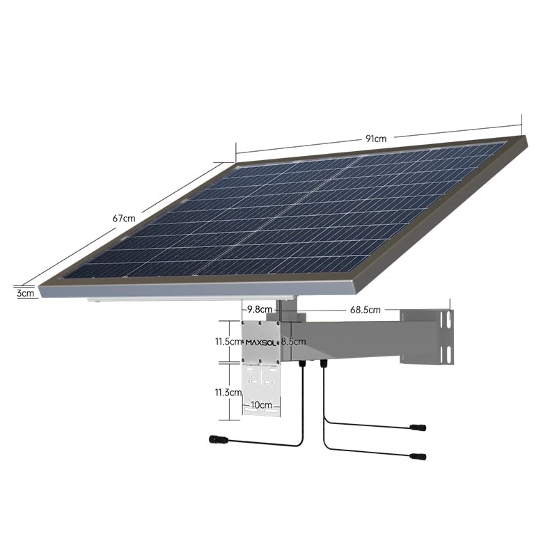
Maxsol’s linked solar systems use MPPT controllers, but they should be assessed as selection examples rather than assumed compatible with every camera, radio or site design.
The Maxsol CS8040 80W 45Ah 576Wh solar system documents an 80W monocrystalline panel, a 12.8V 45Ah 576Wh LiFePO4 battery, an MPPT controller and three DC12V outputs, with RS485 as an option.
For a higher documented panel and nominal battery-energy configuration, the Maxsol CS12060 120W 60Ah 768Wh solar system lists a 120W monocrystalline panel, a 12.8V 60Ah 768Wh LiFePO4 battery, an MPPT controller and three DC12V outputs, also with optional RS485.
Nominal watt-hours are not the same as usable delivered energy. Actual runtime depends on battery limits, controller behaviour, wiring losses, load profile, temperature, solar input and allowed depth of discharge. Neither configuration should be treated as a universal 24/7 runtime guarantee.
Before selection, confirm the current supplied configuration and datasheet values for:
- Controller PV voltage, current and power limits
- Battery charging and operating temperatures
- Charge and discharge protection
- DC output ratings and required port count
- RS485 inclusion if remote management is needed
- Environmental installation requirements
- Cable distance and voltage drop
- Continuous, peak and start-up load demand
The practical next step is to compare the two Maxsol examples against the project’s DC port count, actual load, panel and device cable distances, energy requirement, outdoor environment and management needs. Select the controller approach only after confirming that the panel, battery, BMS and load limits work together as one system.