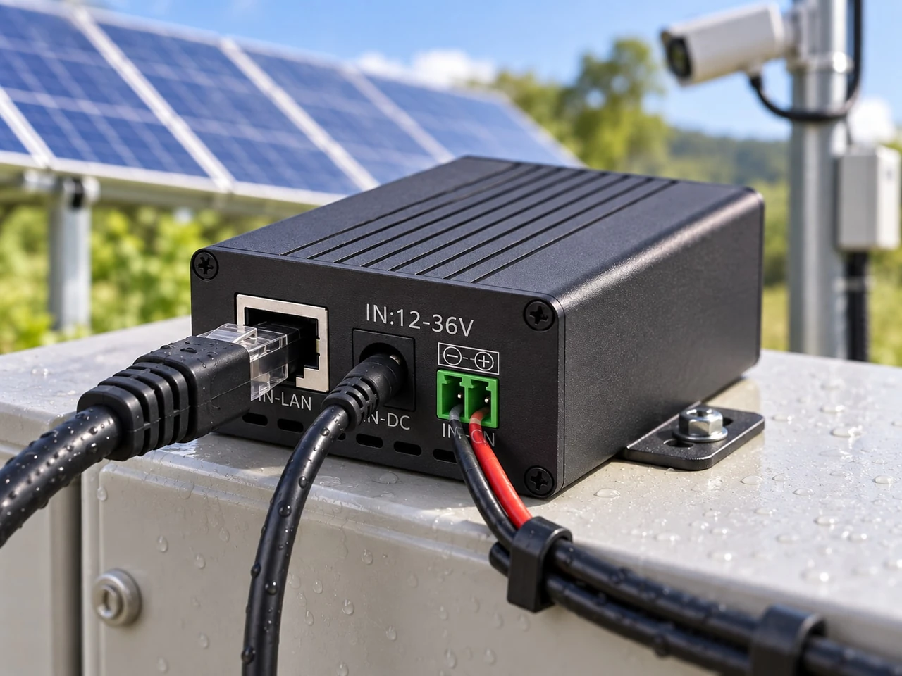
How to Size Solar Power for an Outdoor PoE Device
Calculate daily PoE energy, battery storage and design-month solar input while allowing for converter, cable and auxiliary losses at outdoor sites.
By Maxsol Team

To calculate solar power requirements for an outdoor PoE device, first measure the complete load at the operating point, convert it into watt-hours per day, and then account for converter, cable and auxiliary losses. Battery capacity depends on the required autonomy and usable storage assumptions, while solar-panel capacity depends on the site’s design-month peak sun hours and solar-path efficiency.
Keep energy sizing separate from PoE compatibility. A solar system may have enough watt-hours but still be unsuitable if the converter voltage, polarity, pinout, power limit or PoE protocol does not match the powered device.
Define the complete PoE load and duty cycle
Start with every device that will draw energy from the off-grid system. Depending on the architecture, this may include:
- One or more IP cameras
- A wireless access point or CPE bridge
- A PoE switch or injector
- A DC-to-PoE converter
- A router, modem or network controller
- Heaters, fans, illuminators or other auxiliaries
- Cabinet monitoring, relays or surge-protection electronics that consume power
Do not size the system from a camera’s headline wattage alone. Some powered devices change consumption according to operating mode. An outdoor camera, for example, may draw more power when its infrared illuminator, heater, motor or analytics processor is active.
For each load, record:
- Operating voltage
- Measured or specified power in each mode
- Hours per day in each mode
- Whether the load is continuous, scheduled or event-driven
- Whether the measurement is at the powered device, PoE source or battery input
The measurement location matters because it determines which losses are already included.
Use measured power where practical
A nameplate or data-sheet maximum is useful for checking electrical limits, but it may not represent normal daily consumption. Field measurement provides a stronger basis for energy sizing when the system is available for testing.
Measure the system under representative conditions, including:
- Day and night camera operation
- Infrared illumination active
- Wireless transmission under realistic traffic
- Device start-up
- Pan, tilt or zoom movement where applicable
- Low-temperature heating or ventilation if installed
- Full intended port load on a PoE switch
If measurement is not possible, use the manufacturer’s applicable maximum or operating figures and document the source. Do not substitute the PoE class limit for actual energy demand unless it is the only defensible value available.
For multi-camera projects, calculate the source-side PoE budget separately. The guide to calculating a PoE power budget for security cameras explains how to compare per-port demand, total switch capacity and power overhead.
Build a duty-cycle table
A simple schedule prevents a variable load from being treated as either permanently low or permanently at maximum.
| Load or operating mode | Power | Hours per day | Daily energy |
|---|---|---|---|
| Device in daytime mode | (P_1) W | (t_1) h | (P_1 \times t_1) Wh |
| Device in night mode | (P_2) W | (t_2) h | (P_2 \times t_2) Wh |
| Auxiliary network load | (P_3) W | (t_3) h | (P_3 \times t_3) Wh |
The operating periods for a single device should normally total 24 hours. Seasonal changes in night length may affect outdoor cameras and lighting, so use the most demanding relevant schedule rather than an annual average that hides the design-month load.
Add converter, cable and auxiliary losses
The powered device is only part of the energy path. A typical DC solar-to-PoE system can include:
Solar panel → charge controller → battery → DC converter or PoE source → Ethernet cable → powered device
Each stage can consume or lose energy. Treat these as explicit inputs rather than hiding them in a broad, unexplained margin.
Converter loss
If the PoE-side demand and assumed converter efficiency are known:
[ P_{\text{converter input}} = \frac{P_{\text{converter output}}}{\eta_{\text{converter}}} ]
Here, (\eta) is written as a decimal. For example, 90% becomes 0.90.
Use an efficiency appropriate to the actual input voltage, output voltage and load. A published maximum efficiency should not automatically be used as the design efficiency because performance can vary across the operating range.
The Maxsol POE24V DC-to-PoE converter accepts 12–36V DC and provides an adjustable 12–57V PoE output, Gigabit Ethernet and an LCD voltage display. Its documented continuous load for 12V-to-48V conversion is at most 30W. The stated conversion efficiency of up to 94% is a maximum, not a guaranteed value for every design condition.
Ethernet cable loss
Cable loss increases with current and conductor resistance. It is affected by:
- Cable length
- Conductor material and gauge
- Connector and termination resistance
- PoE voltage
- Device current
- Ambient and cable temperature
The most practical method is to measure power at both ends under the intended load. If that is not possible, calculate the loop resistance from verified cable data and use:
[ P_{\text{cable loss}} = I^2R ]
where (I) is current and (R) is the relevant circuit resistance.
Do not apply the same percentage to every cable run. A short high-voltage PoE link and a long low-voltage DC run can have very different losses.
Auxiliary consumption
Add all loads that do not appear in the powered-device wattage. Examples include a switch’s own consumption, a modem, a cabinet fan or a controller display.
Be careful not to double-count them. If total battery-input power has already been measured while the complete system is running, downstream converter, cable and auxiliary losses may already be included.
Convert power into daily energy demand
Solar sizing uses energy, not power alone. Watts describe the instantaneous rate of consumption; watt-hours describe the energy consumed over time.
For a constant load:
[ E_{\text{daily}} = P \times 24 ]
For a variable load:
[ E_{\text{daily}} = (P_1 \times t_1) + (P_2 \times t_2) + \cdots ]
Worked calculation for one outdoor PoE load
The following is an illustrative calculation, not a product performance claim or a recommended Philippine design value.
Assume a device is measured at:
- 11W for 12 daytime hours
- 16W for 12 night-time hours
- 0.8W estimated cable loss during the day
- 1.1W estimated cable loss at night
- 90% assumed converter efficiency
- 3.5W of continuous auxiliary consumption
First calculate energy at the converter’s PoE output:
[ (11 + 0.8) \times 12 = 141.6Wh ]
[ (16 + 1.1) \times 12 = 205.2Wh ]
[ E_{\text{PoE output}} = 346.8Wh/day ]
Now account for the assumed converter efficiency:
[ E_{\text{converter input}} = \frac{346.8}{0.90} = 385.3Wh/day ]
Then add the auxiliary load:
[ 3.5W \times 24h = 84Wh/day ]
Total daily demand is therefore:
[ 385.3 + 84 = 469.3Wh/day ]
Round only after the major calculations. Excessive early rounding can become significant across several loads.
Multiple PoE devices
For several devices, calculate daily energy per load and add the results:
[ E_{\text{site}} = E_{\text{device 1}} + E_{\text{device 2}} + \cdots + E_{\text{auxiliary}} ]
Also check simultaneous power. A battery may contain enough daily energy while the converter or PoE switch is unable to supply the combined instantaneous load.
Select autonomy and usable storage assumptions
Autonomy is the period the battery is expected to support the load without sufficient solar charging. It is usually stated in days or hours.
The correct target depends on project requirements, including:
- Consequence of an outage
- Seasonal cloud conditions at the specific site
- Access for inspection or recovery
- Whether load reduction is possible
- Required recovery time after poor weather
- Battery operating conditions and ageing assumptions
There is no universal autonomy figure for every outdoor PoE installation in the Philippines. A remote surveillance site with difficult access may require a different design from a non-critical network link with backup connectivity.
Calculate nominal battery energy
A general storage equation is:
[ E_{\text{battery nominal}} = \frac{E_{\text{daily}} \times D} {F_{\text{usable}} \times \eta_{\text{storage path}}} ]
where:
- (D) is autonomy in days
- (F_{\text{usable}}) is the selected usable fraction of nominal storage
- (\eta_{\text{storage path}}) accounts for applicable battery-side delivery losses
For the worked daily load of 469.3Wh, suppose the project—not a product specification—selects:
- Two days of autonomy
- 80% usable storage
- 90% battery-path delivery efficiency
Then:
[ E_{\text{battery nominal}} = \frac{469.3 \times 2}{0.80 \times 0.90} = 1,303.6Wh ]
These percentages are illustrative assumptions only. Replace them with values justified for the selected battery, temperature range, discharge rate, controller behaviour, ageing policy and required service life.
If daily energy has been measured directly at the battery terminals, check which losses are already captured before applying another efficiency factor.
Nominal watt-hours are not delivered watt-hours
A battery’s nominal watt-hour rating should not be treated as guaranteed usable energy. Actual delivered energy can be influenced by:
- Discharge limits
- Battery management system cut-off
- Load current
- Temperature
- Conversion losses
- Cable voltage drop
- Battery age and condition
- The system’s minimum acceptable operating voltage
For calculation comparison, the Maxsol CS8040 80W and 576Wh solar system documents an 80W monocrystalline panel, 12.8V 45Ah 576Wh LiFePO4 battery, MPPT controller and three DC12V outputs.
The Maxsol CS12060 120W and 768Wh solar system documents a 120W monocrystalline panel, 12.8V 60Ah 768Wh LiFePO4 battery, MPPT controller and three DC12V outputs.
These nominal figures can be entered into a project comparison, but they do not establish usable capacity, autonomy or compatibility with a particular PoE device.
| Calculation input | CS8040 documented value | CS12060 documented value |
|---|---|---|
| Solar panel | 80W monocrystalline | 120W monocrystalline |
| Nominal battery | 576Wh | 768Wh |
| Battery voltage and capacity | 12.8V, 45Ah | 12.8V, 60Ah |
| Controller | MPPT | MPPT |
| Documented DC outputs | Three DC12V outputs | Three DC12V outputs |
Compare the project’s calculated nominal storage requirement with the documented battery energy, then evaluate usable energy using approved battery assumptions. Do not estimate runtime simply by dividing nominal watt-hours by device watts.
For a broader CCTV architecture covering several loads, see the guide to sizing an off-grid solar power system for CCTV.
Estimate design-month solar input
The panel must supply the daily load during the selected design month, not merely under ideal annual-average conditions.
Use:
[ P_{\text{array}} = \frac{E_{\text{daily}}} {H_{\text{design month}} \times \eta_{\text{solar path}}} ]
where:
- (H_{\text{design month}}) is verified peak sun hours for the site and design month
- (\eta_{\text{solar path}}) combines justified losses between the panel and usable load energy
Solar-path assumptions may need to cover controller conversion, wiring, module temperature, dirt, mismatch, orientation and other project-specific effects. Keep these assumptions visible so the design can be reviewed.
Do not use an unverified national peak-sun-hours figure. Conditions vary by location, season, panel orientation, horizon, nearby vegetation and structures. In the Philippines, seasonal cloud and heavy rain can also make a yearly average unsuitable for a critical design month.
Illustrative array calculation
Using the example daily demand of 469.3Wh, suppose a designer has independently established:
- 3.5 design-month peak sun hours
- 75% combined solar-path efficiency
These figures are hypothetical and are not recommended local values.
[ P_{\text{array}} = \frac{469.3}{3.5 \times 0.75} = 178.8W ]
The theoretical one-day energy-balance result is approximately 179W. The selected array would then need to be assessed against available panel sizes, site conditions and required recovery performance.
Allow for battery recovery
An array that only replaces an average day’s load may take too long to restore the battery after poor weather. If recovery is required, add the energy to be replenished over the selected recovery period:
[ P_{\text{array}} = \frac{E_{\text{daily}} + \left(E_{\text{recovery}} \div N_{\text{recovery days}}\right)} {H_{\text{design month}} \times \eta_{\text{solar path}}} ]
For example, recovering one 469.3Wh deficit over three qualifying solar days would add:
[ 469.3 \div 3 = 156.4Wh/day ]
Using the same hypothetical solar assumptions:
[ P_{\text{array}} = \frac{469.3 + 156.4}{3.5 \times 0.75} = 238.4W ]
This shows why panel sizing and battery sizing should not be treated as the same decision. More storage improves autonomy, while sufficient array input is needed to support the daily load and restore depleted storage.
Verify voltage, protocol and commissioning measurements
Energy calculations do not prove PoE compatibility. Before connecting equipment, verify the entire electrical and network interface.
Check the powered device
Confirm:
- Required input voltage range
- Maximum and normal power
- PoE standard or passive-power requirement
- Polarity and powered pairs
- Start-up or inrush demand
- Connector and grounding requirements
Check the converter or PoE source
Confirm:
- DC input range across battery charge and discharge conditions
- Output voltage setting
- Continuous output-power limit
- Polarity and pinout
- Ethernet speed requirement
- Whether powered-device detection or negotiation is provided
- Behaviour during low voltage, overload and restart
For the POE24V, IEEE powered-device detection or negotiation is not established by the documented facts. Verify voltage, polarity, pinout and protocol compatibility before connection. The linked solar systems and converter are calculation examples, not a tested compatible bundle.
Commission the installed system
After installation, measure rather than assume. Record:
- Battery voltage at rest and under peak load
- Converter input current and voltage
- PoE output voltage under load
- Powered-device voltage where measurable
- Day and night energy consumption
- Cable voltage drop at maximum demand
- Solar charging energy under representative conditions
- Low-voltage cut-off and restart behaviour
- Network stability during load transitions
A DC clamp meter, suitable multimeter, PoE tester and energy logger can help identify discrepancies between the design model and the installed system. Instruments and test methods must be appropriate for the circuit and used safely.
Common sizing mistakes to avoid
- Using watts as if they were watt-hours. A 15W device running for 24 hours consumes 360Wh before losses.
- Sizing only from the powered device. Converters, switches, cables and auxiliaries also require energy.
- Using maximum converter efficiency as a guaranteed value. Efficiency varies with voltage and load.
- Treating nominal battery capacity as fully usable. Apply documented, project-approved storage assumptions.
- Using annual-average solar input for the critical month. Base the array on verified site and seasonal data.
- Ignoring recovery time. Daily energy balance alone may not restore a depleted battery promptly.
- Confusing PoE power budget with solar energy capacity. One checks instantaneous delivery; the other checks energy over time.
- Assuming matching connectors prove compatibility. Voltage, polarity, pinout and protocol must all be verified.
- Adding broad margins without explanation. State each loss, environmental allowance and design decision separately.
- Skipping post-installation measurement. Field data is needed to validate the assumptions and refine alarms or load controls.
Final calculation checklist
Before selecting equipment, make sure the design file includes:
- Measured or defensible power for every load
- Day, night and event-driven duty cycles
- Cable-loss calculation or measurement
- Converter efficiency assumption at the intended operating point
- Auxiliary and network-device consumption
- Total watt-hours per day
- Required autonomy
- Usable battery fraction and storage-path assumptions
- Verified design-month peak sun hours
- Solar-path efficiency assumptions
- Battery recovery requirement
- Simultaneous peak-power check
- PoE voltage, polarity, pinout and protocol verification
- Commissioning measurements and acceptance limits
As a practical next step, compare the linked Maxsol solar systems and DC-to-PoE converter against the project’s port count, measured load, cable distance, power demand, outdoor environment and network-management requirements. Use the calculated daily energy, nominal storage target and design-month array requirement as the basis for comparison rather than relying on panel watts or battery watt-hours alone.