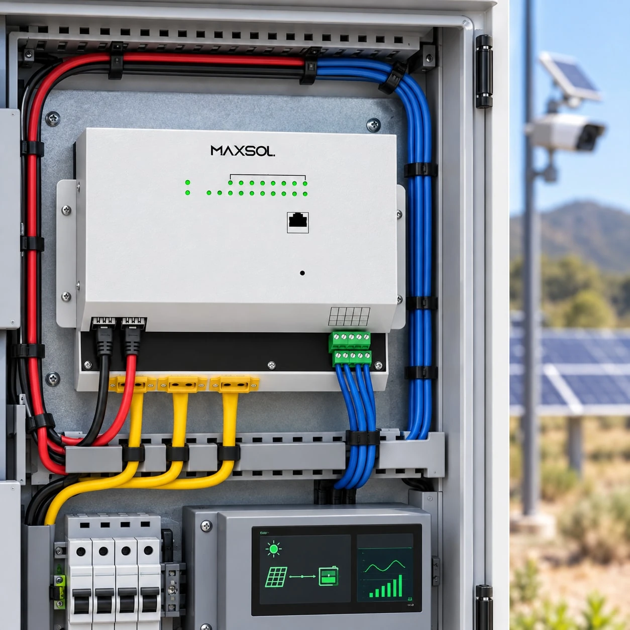
Building a 24/7 Solar-Powered Network at Remote Sites
Learn how to size solar, batteries, PoE, wireless backhaul and monitoring for a reliable remote network, including recovery and acceptance testing.
By Maxsol Team

A 24/7 solar-powered network for remote locations must be designed as a complete energy and communications system—not assembled by matching headline wattages. Start by defining which services must remain online, calculate every continuous and peak load, then size the battery and solar array against the site’s worst credible solar period and required recovery time.
Continuous operation also depends on managed PoE distribution, a viable backhaul, remote monitoring, controlled load shedding, restart sequencing and practical maintenance access. No solar kit or network device can guarantee universal uptime; availability is an engineering objective supported by testing and an operations plan.
Define network services and an availability objective
Begin with the service outcome rather than a product list. A remote network may support IP cameras, environmental sensors, access control, public Wi-Fi, point-to-point backhaul or a combination of these. Their importance and acceptable outage periods are not necessarily the same.
Document the following for every service:
- Devices required to deliver it
- Whether it must operate continuously
- Maximum acceptable interruption
- Whether recorded data can be stored locally during a backhaul failure
- Recovery priority after a low-battery shutdown
- Person or team responsible for responding to alarms
- Access time and constraints for on-site repair
This process separates critical communications from useful but deferrable loads. For example, the core switch and backhaul may need to remain energised while supplementary lighting, secondary cameras or public access points can be disconnected during an energy shortage.
Treat availability as a measurable project requirement. Instead of stating that a site must “never go offline”, define pass-or-fail conditions such as:
- Which services must survive the specified low-solar design period
- Minimum battery reserve before non-critical loads are shed
- Permitted recovery behaviour after solar input returns
- Maximum delay before critical network equipment reconnects
- Alarm conditions that must be reported remotely
- Conditions requiring a site visit
The objective should also distinguish a power outage from a network outage. A camera may remain powered while its wireless link is unavailable, or the backhaul may work while a PoE endpoint has failed. Monitoring must identify these separately.
Inventory continuous, intermittent and startup loads
A reliable energy calculation must include the entire site, not only the advertised consumption of the main devices. Controllers, switches, radios, heaters, fans, converters and monitoring equipment all contribute to daily energy use.
Classify loads into three groups:
| Load type | Typical examples | What to record |
|---|---|---|
| Continuous | Managed switch, network controller, backhaul radio, essential cameras | Normal watts, maximum watts and 24-hour energy |
| Intermittent | Illuminators, access-control motors, maintenance lights, fans | Power, operating schedule and worst-case duty cycle |
| Startup or peak | Radios booting, camera infrared switching, multiple PoE devices restarting | Peak demand, duration and simultaneous-start risk |
For each device, confirm input voltage, normal consumption, maximum consumption and operating schedule. Where possible, measure actual equipment under representative conditions. A nameplate maximum may overstate ordinary use, while a typical-consumption figure may omit startup peaks or optional functions.
Calculate daily energy using:
Daily energy in watt-hours = power in watts × operating hours per day
For intermittent equipment, use its credible worst-case operating duration rather than an optimistic average. Add conversion losses and the standby consumption of equipment between the solar controller and network endpoints.
Check the complete PoE power path
A PoE endpoint’s stated consumption is not the whole upstream load. The energy system must supply:
- The powered device
- Losses in the Ethernet cable
- Internal consumption and conversion losses in the PoE switch
- Any DC converter between the battery and switch
- Protection, monitoring and control equipment
Cable length, conductor size, connection quality and operating voltage affect delivered power. Verify that the switch can provide the required power per port and across all active ports simultaneously.
For a more detailed network-side planning process, see the solar PoE switch guide for remote IP camera networks.
Do not overlook environmental loads
Outdoor enclosures may require ventilation, heating, dehumidification or other environmental controls depending on the equipment and site. These loads can be intermittent but substantial.
For installations in the Philippines, designers should account for site-specific heat, humidity, salt exposure, heavy rain, vegetation and seasonal cloud conditions. Do not use a national average as a substitute for measurements or a credible solar dataset for the actual location.
Size worst-month storage, solar and recharge capacity
Solar sizing should be based on usable delivered energy during the design month, not only nominal panel watts and battery watt-hours.
The basic process is:
- Calculate the site’s worst-case daily energy requirement.
- Select the required low-solar autonomy period.
- Determine usable battery energy after all operating limits and losses.
- Size the solar array for the site’s worst design month.
- Confirm that the array can power the live load and recharge the battery.
- Check controller voltage, current and power limits.
- Repeat the calculation for degraded or partially unavailable conditions.
Nominal energy is not usable delivered energy
A battery’s nominal energy is commonly estimated as:
Nominal watt-hours = nominal voltage × ampere-hours
That figure is not the energy that will reach the network devices. Usable delivered energy is lower after considering:
- Permitted depth of discharge
- Battery-management cut-off limits
- Temperature effects
- Battery ageing allowance
- DC conversion losses
- Cable and connection losses
- Controller consumption
- Required emergency reserve
- Voltage limits of the connected network equipment
The Maxsol CS400150 solar system documents a 400W panel configuration using two 200W modules, a 12.8V 150Ah, 1920Wh LiFePO4 battery, MPPT control and four DC12V outputs. These are nominal architecture details for evaluation; they do not establish the runtime of a particular network. Runtime depends on the measured load, operating conditions, reserve settings and system losses.
Size for recovery, not just survival
A battery may carry the load through a cloudy interval but remain at a low state of charge afterwards. If the solar array can only cover the current network load, the battery may not recover before the next poor-weather period.
The available solar energy must therefore support both:
- The network’s energy consumption during daylight and overnight
- The project’s required battery recharge within its specified recovery window
Use site-specific worst-month solar input and apply appropriate allowances for module temperature, orientation, dirt, shading, controller losses, wiring and other system losses. Confirm that the controller can accept the proposed photovoltaic open-circuit voltage, operating voltage, current and total power under expected conditions.
Analyse partial failures as well. Ask what happens if one panel is shaded, a cable develops resistance, or a module is unavailable. The correct design response may be a larger energy margin, a reduced emergency load or a planned maintenance intervention—not an unsupported uptime claim.
Common calculation and installation errors are covered in this guide to off-grid solar power design mistakes.
Design PoE switching, backhaul and load priority
The network architecture should maintain critical connectivity while allowing non-essential loads to be controlled. A managed PoE switch is particularly useful when it can report port conditions, isolate failed devices and switch selected loads according to energy state.
Build a load-priority table
Assign each powered device to a recovery and load-shedding tier:
| Priority | Example role | Low-energy action | Recovery order |
|---|---|---|---|
| Tier 1 | Core switch, primary backhaul, essential controller | Keep online until the protected shutdown threshold | Start first |
| Tier 2 | Essential surveillance or operational endpoints | Shed only after non-critical loads | Start after core connectivity is stable |
| Tier 3 | Secondary cameras, supplementary access points | Disconnect early to preserve autonomy | Restart after the battery reaches a defined recovery level |
| Tier 4 | Convenience or maintenance loads | Keep off during energy constraint | Restart last or manually |
The exact assignments depend on the project. A surveillance site may prioritise recording differently from a community network or telemetry station.
Avoid restoring every PoE port at once. Simultaneous startup can create a short power peak, trigger protection or cause repeated restart cycles. A controlled sequence should energise the switch and management path first, then the backhaul, followed by critical endpoints and finally deferrable loads.
Verify voltage compatibility before selecting equipment
The Maxsol IOT2802SFG-S managed solar industrial PoE switch documents eight Gigabit PoE ports, two SFP ports, a 120W PoE budget, 90W BT support, PV and battery monitoring, and configurable 24V or 48V PoE on ports 3–4. Its documented PV and battery input range is DC22–29.2V.
That input requirement is important: a 12.8V battery kit such as the CS400150 is not a direct compatible input for a DC22–29.2V device. The two linked products are alternative architecture examples, not a validated bundle. Do not connect them together without a correctly engineered power architecture and verification of voltage range, controller limits, grounding, protection and all interfaces.
For any switch, confirm:
- Total PoE budget and per-port requirement
- Supported PoE mode for every endpoint
- Input voltage range
- SFP module and fibre compatibility, where used
- Management and monitoring functions
- Surge and grounding design
- Operating environment and enclosure needs
- Behaviour after undervoltage or power interruption
- Ability to schedule or remotely restart individual ports
Engineer the wireless backhaul separately
A radio’s distance label does not prove that a link will work at the site. Backhaul design must consider line of sight, Fresnel-zone clearance, terrain, vegetation, mounting movement, interference, antenna alignment, cable losses and permitted radio settings.
The Maxsol CPE295 5.8GHz wireless CPE documents 5.8GHz operation, a 2×2 14dBi directional MIMO antenna, one Gigabit LAN port and 6.5W full-load consumption. Use these documented details as inputs to a link and energy assessment, not as proof of achievable range or throughput at a particular location.
A pre-installation radio survey is preferable. Where that is not possible, obtain terrain information, mounting heights and interference observations, then validate the installed path before final acceptance.
Monitor energy, faults and controlled recovery
Remote monitoring should answer three questions: Is the site generating enough energy? Is the network functioning? Can the system recover without an immediate visit?
Useful energy data may include:
- PV voltage and current
- Battery voltage, current and state information
- Charge-controller state
- Low-voltage and overvoltage events
- Load current
- Enclosure temperature
- History of charging, load shedding and shutdowns
Useful network data may include:
- Switch and port status
- PoE delivery state
- Endpoint reachability
- Backhaul signal and link state
- Traffic or error changes
- Reboot history
- Configuration changes
Do not depend on a single remote alarm path. If the backhaul itself fails, cloud-based monitoring may only report that the entire site is unreachable. Local event logging allows technicians to determine whether the cause was low energy, a radio outage, a switch restart or an endpoint fault after connectivity returns.
Prevent repeated low-voltage restart cycles
An uncontrolled system may shut down at low voltage, restart as soon as sunlight raises the voltage slightly, then shut down again when the load reconnects. Repeated cycling can prevent a stable recovery and complicate diagnosis.
A controlled recovery policy should define:
- Protected shutdown or load-shedding thresholds
- A higher recovery threshold than the shutdown threshold
- A minimum stable charging condition before restart
- A delay before energising network loads
- A staged sequence for PoE ports
- A lockout or escalation rule after repeated failed restarts
Settings must follow the battery, controller and connected-equipment requirements. Voltage alone may not accurately represent available battery energy under every condition, so use the best supported measurements available from the selected architecture.
Test, hand over and maintain the remote site
Acceptance testing should demonstrate system behaviour under normal operation, low-solar conditions, communications faults and controlled recovery. Simply confirming that devices turn on in full sun is not enough.
Run a hypothetical worst-month acceptance test
Build the test around the project’s approved worst-month energy model. The exact duration and thresholds should come from the site design rather than a generic figure.
A practical test sequence is:
- Establish a baseline. Record PV input, battery condition, every active load and normal network performance.
- Apply the design load. Operate all continuous services and the specified worst-case intermittent loads.
- Simulate the approved low-solar period. Limit charging in a controlled way that represents the design scenario without bypassing protection.
- Confirm load shedding. Verify that lower-priority devices disconnect in the intended order.
- Check critical service continuity. Confirm which services remain available and whether local recording continues if the backhaul is interrupted.
- Reach the protected shutdown condition if required by the test plan. Verify that the system shuts down cleanly rather than repeatedly cycling.
- Restore representative solar input. Confirm that charging begins and restart is delayed until the recovery conditions are satisfied.
- Observe staged restart. Check that the core network, backhaul and endpoints return in the approved sequence.
- Measure recharge performance. Compare actual recovery against the design window while the operating load remains connected.
- Review logs and alarms. Ensure the recorded events allow a remote operator to understand what occurred.
Acceptance passes only if the measured results meet the project’s defined criteria. A test conducted under stronger solar conditions does not by itself validate worst-month performance.
Prepare a usable handover package
Provide the operator with:
- Final load schedule and power calculations
- Network and power diagrams
- Port assignments and load priorities
- Device addresses and management access procedure
- Controller and restart settings
- Alarm thresholds and escalation steps
- Grounding and protection layout
- Installed cable and connector records
- Configuration backups
- Spare-parts list
- Maintenance schedule
- Safe isolation and restart procedure
Remote sites should also be designed for physical serviceability. Allow access to fuses, breakers, connectors, batteries, controllers, switches and radio cabling without dismantling unrelated equipment.
Plan how technicians will reach the site, what tools and spares they must carry, and which faults can realistically be resolved in one visit. Common spares may include appropriately specified fuses, connectors, surge-protection components, patch leads, power converters or preconfigured network equipment, depending on the architecture.
Maintenance intervals should reflect the actual environment. Inspections may need to cover panel cleanliness and shading, corrosion, water entry, mounting movement, cable damage, enclosure seals, grounding connections, battery records, radio alignment, event logs and configuration backups.
Final design checklist
Before approving a 24/7 solar-powered network for a remote location, confirm that:
- The critical services and availability objective are documented.
- Continuous, intermittent and startup loads have been measured or conservatively specified.
- Nominal battery energy has not been treated as fully usable delivered energy.
- Solar sizing uses credible worst-month site data.
- Recharge capacity has been assessed alongside autonomy.
- Every input voltage and interface is compatible.
- PoE budgets have been checked per port and in total.
- The wireless path has been surveyed or otherwise validated.
- Load shedding and staged recovery are configured.
- Energy and network faults can be distinguished remotely.
- The system has passed an agreed low-solar and recovery test.
- Operators have diagrams, settings, spares and maintenance procedures.
As a practical next step, compare the linked Maxsol models against your required port count, measured load, radio distance, power architecture, environmental conditions and management needs. Verify every voltage, controller limit and interface before treating any products as part of the same system.